Part 2 of this article focuses on the relative merits CT-ESPs, to help you decide whether they are worth considering as an alternative to conventional (tubing) deployed ESPs for your field(s).
Background
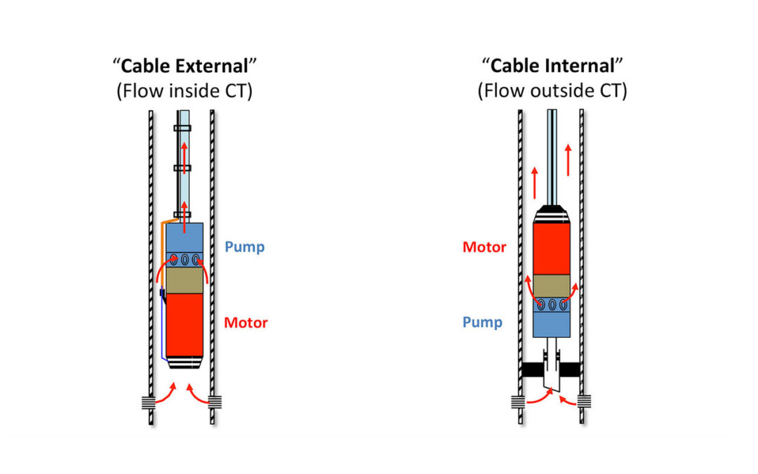
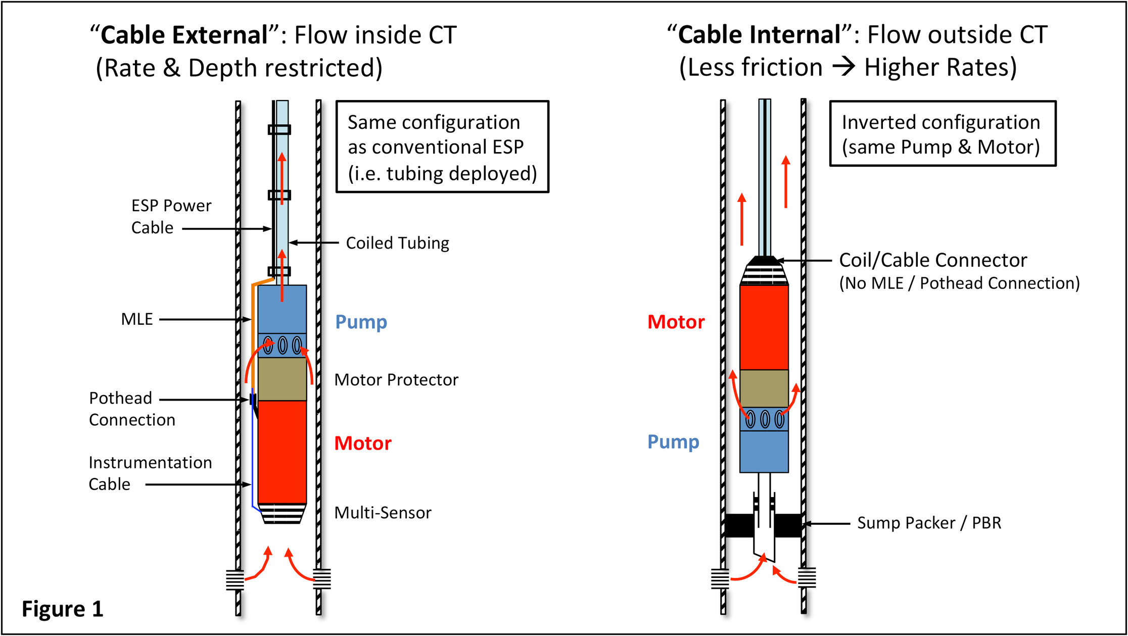
Part 1 of this article summarises the historical development and current status of CT-ESP technology; it describes “cable-external” and “cable-internal” systems (Figure 1):
Here in Part 2, I dive a little deeper to discuss the benefits, limitations and applications of CT-ESPs… and attempt to answer the question posed in the title.
Relative Merits of Cable-External CT-ESPs
Configuration of the cable-external ESP assembly is essentially the same as a conventional ESP, with the exception that the pump discharge head is attached via a special connector that supports the ESP string weight and routes production inside the CT.
Advantages:
- Simple system – same technology as conventional ESPs (same Power Cable, same ESP equipment).
- Shorter WO duration than for rig-deployed ESPs.
- CTU availability: (Usually) less downtime for replacement of failed equipment compared to waiting for a WO rig.
- Conventional Wellheads and Power Cable feed-through assemblies can be used.
- Production casing is protected from any corrosives in well fluids – production from ESP to surface is inside the CT.
- Compared to cable-internal systems, no packer is required.
Disadvantages:
- Production rate are limited by friction losses through the Coil.
- Offshore deployment:
- Larger CT sizes can be operationally challenging because of the increased distance required between Coil and Injector Head (i.e. to avoid excessive bending during deployment/retrieval when the Coil feeds over the gooseneck).
- Additional deck space needed to accommodate separate CT and ESP Power Cable Spoolers.
- Depth limitation (Power Cable must support its own weight): If your reservoir is deeper than 2,000 m (ca. 6,500 ft) then be sure to check feasibility with your Supplier!
- Live well intervention is not possible due to the external location of the Power Cable (unable to effect a proper seal with the BOP during tripping).
- Corrosion: CT materials are typically not rated for long-term exposure to corrosive well effluents, especially to CO2. Various corrosion resistant alloy (CRA) materials such as 13Cr (and higher spec such as Nickel based) are available but add to costs.
Relative Merits of Cable-Internal CT-ESPs
As outlined in Part 1, cable-internal systems typically utilise inverted* ESPs (motor above pump) that produce to surface via the annulus, either as casing production or inside pre-deployed tubing. The ESP Power Cable is inside – and therefore protected by – the Coil. In case hydraulic lines are required (e.g. for downhole chemical injection) or separate instrumentation lines for downhole pressure/temperature monitoring, they are also contained within the CT. Pre-requisite for annular flow is some form of isolation below the CT-ESP such as a sump packer (ref. Figure 1, above).
[*At least one CT/Cable Supplier offers a hybrid variation that utilises a conventional ESP configuration (i.e. pump above motor) and can be run with any brand of ESP equipped with a “standard” pump discharge head. In this case the annular seal is effected either by inclusion of a hydraulic packer just above the ESP or, if a pump seat nipple is incorporated in pre-deployed tubing, an API hold-down tool.]
Advantages:
- Live well intervention is possible.
- Shorter WO duration compared to conventional ESPs.
- CTU availability: Less downtime for replacement of failed equipment compared to waiting for a WO rig.
- Protection of ESP Power Cable and capillary lines (e.g. for downhole chemical injection or instrumentation) during deployment and retrieval operations.
- Protection of ESP Power Cable and capillary lines from corrosives in well fluids and any free gas (e.g. vented, or coming out of solution either during production or shutdowns.)
- Elimination of the MLE and pothead connection reduces potential electrical failure locations.
- Elimination of cable bands – a common source of junk as they often break-off during ESP installation/retrieval operations and subsequently block pump intakes.
- Similar or higher flow rates compared to an equivalently sized conventional ESP.
- Elimination of the separate, additional Cable Spooler required by cable-external systems.
Disadvantages:
- Additional operational complexity compared to other systems (especially conventional ESPs).
- ESP equipment configuration is more complex than both conventional ESPs and cable-external systems. Annular isolation required (e.g. packer).
- Horizontal tree required or modification of conventional Wellhead (additional spool plus some specialised equipment).
- Cost: While most of the ESP components are comparable to conventional ESP equipment, the Coil is significantly more expensive due manufacturing costs associated with installing the Power Cable inside. Additional costs for Wellhead (mods or new), and possibly for production tubing string.
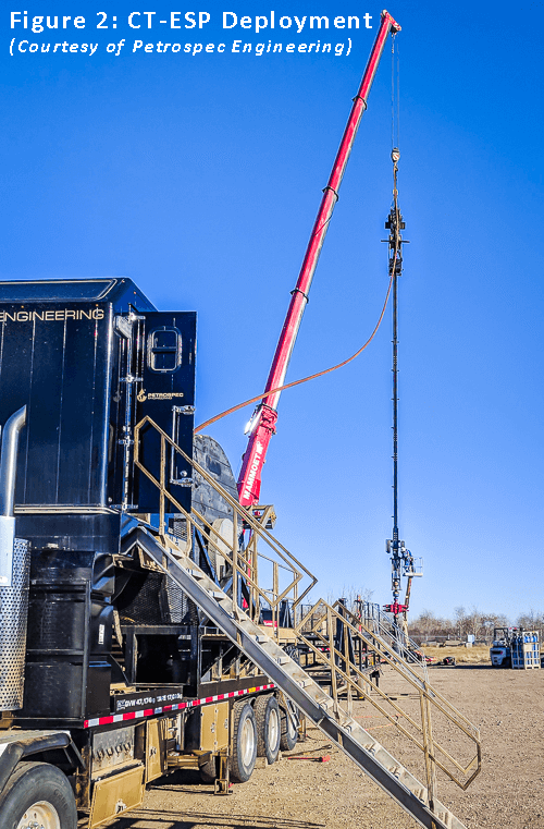
- Crane capacity: Coil weight (up to 8kg/m has been reported), plus the added weight of the CT reel might potentially exceed capacity of some cranes, especially offshore. Lift heights should also be checked and verified: Some systems require the entire ESP assembly length (rather than ESP component sections) to be lifted, plus allowance for BOPs and Injector Head (Figure 2).
- Length: Some (older) manufacturing processes require the CT to be laid out horizontally while the Power Cable is pulled into it; the resulting frictional forces have limited individual string lengths to ca. 2,500 m (ca. 8,200 ft). Manufacturing processes continue to improve therefore, depending on the Supplier and intended deployment, this may or may not be an issue.
- Corrosion: CT materials are typically not rated for long-term exposure to corrosive well effluents, especially to CO2. Various corrosion resistant alloy (CRA) materials such as 13Cr (and higher spec such as Nickel based) are available but add to costs.
CT-ESP Applications & General Limitations
I’m assuming that if you are considering CT-ESPs then probably it’s the cable-internal system. Let’s start with the elephant in the room: if you think this is a cheap solution then think again. As mentioned above, be prepared to dig deep into your budget for the Coil and remember to put some cash aside for those Wellhead mods (or more cash for new, horizontal trees). Then there’s the WO rig time required for the initial installation, for instance to pre-install tubing if casing production is not acceptable, e.g. due to well integrity concerns.
On the plus side, the fact that the ESP Power Cable is protected from mechanical damage during deployment and is not exposed to well fluids (no risk of gas imbibing into the Cable if it is normally vented up the annulus) is a big advantage. Capillary lines (e.g. chemical injection, instrumentation), if required, can also be contained within the Coil and therefore protected by it.
Also, depending on time between pulls and well conditions (e.g. presence of corrosives vs. materials used), it should be possible to re-use the Coil – possibly several times, thereby reducing Life-Cycle costs.
Instrumentation: Most, but not all CT-ESP Suppliers offer Multi-Sensors. They are usually located at the top of the inverted ESP, between motor and the Coil connector. Discharge conditions are recorded; a capillary line must be run down to the pump in order to measure intake conditions.
Interventions: When considering candidates for this technology, remember there is no option for reservoir access while the ESP is in-situ, i.e. no Y-tool equivalent (by-pass system), so no possibility for production logs (e.g. PLTs), re-perforating, water shut-offs, etc.
Of course the CT-ESP can be quickly and easily retrieved, and it doesn’t require a WO rig – after all, that’s the main attraction! Bear in mind that if space is an issue (e.g. offshore), in order to gain access to rig-up over the Wellhead for whatever activities are to be conducted, you’ll need to move the ESP assembly away from the Wellhead area and, depending on the intervention planned, possibly also the Injector Head, Jacking Frame (access platform), CT Reel, etc.
Well deviation is generally not an issue provided the Coil can reach the target depth. Indeed, CT-ESPs have been operated successfully in horizontal wells[1]. For deployment they are subject to similar bending restrictions (dogleg severity) as conventional ESPs, and must also be set in a tangent section.
The additional operational complexity compared to other systems (especially conventional ESPs) means that careful planning is required; even Operators already familiar with ESPs may be faced with more internal interfaces, e.g. the (ESP) planning department, the WO Team, Well Services and Production Departments may all have separate reporting structures.
So, are CT-ESPs worth Considering?
Most CT-ESP applications that I am aware of were instigated by the desire to reduce WO rig usage. Mainly this was aimed at cutting WO costs; however, recently I was involved in one field in which the primary driver was to free up rig capacity to meet other commitments and, as a secondary effect, to reduce downtime (i.e. lost production!) because rig availability constraints routinely meant delays of several months to replace failed ESPs.
As highlighted in Part 1, CT-ESPs have been available for several decades so I think it’s fair to say the concept is more than proven. Technical feasibility is therefore application specific. As an example, if high rates are desired but casing production is not an option (e.g. due to well integrity concerns), the basic assessment would include evaluation of
- What size of production tubing needs to be pre-installed?
- Are desired rates available from the size of ESP will physically fit, based on
- Pump capacity
- Motor HP
- Equipment physical limits such as shaft strength
In terms of equipment availability, note that the feasible motor HP for an inverted system may be less than it’s conventional equivalent; do not assume that if desired flow rates are within a pump’s ROR (Recommended Operating Range) that a suitable motor size (capacity) will be found. You will need to discuss specifics with your CT-ESP Supplier because the information might not be published in the Manufacturer’s Catalogues.
If measurement of Pump Intake Pressure (PIP) is important, be aware that in some cases this may not be possible, either because the Supplier doesn’t offer it or because of insufficient clearance between motor (or motor protector) and tubing/casing.
Assuming there are no electrical issues (e.g. harmonics, voltage spikes) then it is reasonable to expect the life of the Power Cable, protected from well fluids inside the Coil, should exceed that of the ESP. Unless there are other mitigating circumstances such as a highly corrosive or very hot environment, or even a very long ESP run-life (now there’s a thought!) I would anticipate a positive Coil inspection result.
Even if the Coil has to be replaced, economics may still favour CT-ESPs, especially if a well kill can be avoided. Financially it comes down to how these costs compare to conventional, rig-based ESPs or even other retrieval methods (e.g. hydraulic pulling unit).
It is vital to take a Life-Cycle approach to cost assessment. The initial installation will probably be expensive and require a rig (wellbore preparation, installation of monobore production tubing string…) plus time/cost of Wellhead mods, etc. However, subsequent ESP changeouts with a CTU should be cheaper, especially if the Coil can be re-used.
When comparing with conventional (rig-based) WO costs, don’t forget to factor-in any associated production losses, e.g. the need to close in nearby wells during rig moves, disconnection of nearby flowlines, etc, as well as the production lost from the well itself while waiting for the rig compared to CTU mobilisation**.
[**This assumes a suitably sized, inverted ESP replacement would be available within this timeframe. If that is not the case, maybe it’s time to review your equipment backup policy and/or Contract with your CT-ESP Supplier…]
Opinion: The Future?
Well, if you’ve read this far, congratulations on your stamina! So what do I think? CT-ESPs are currently still very much a niche market but that market is growing. The fact that Baker, Schlumberger and specialist providers such as Petrospec Engineering*** are constantly increasing and further developing their line-up means they certainly think it is. The recent partnership between Baker and Saudi Aramco to develop a smaller Coil size with significantly deeper deployment depths (compared to the previous generation) demonstrates that some major Operators also see potential.
[***These companies are mentioned as examples. There are other CT-ESP equipment Suppliers, especially if you can live without a “live” pull, e.g. if local legislation requires a well to be killed prior to WO.]
My guess is that CT-ESP usage will grow but remain a relatively small portion of the overall ESP market. After all, if you are an Operator, why take on additional complexity and therefore potential risk? Well, the answer is actually quite simple: economics. If you think CT-ESPs might have potential application for your oil field and preliminary cost estimates look promising, then why not try a small-scale pilot project and scale-up over time if results are good? Such an approach would:
- Facilitate a proper assessment under your field specific conditions.
- Provide an opportunity to gain valuable operating experience.
- Allow you to refine field specific installation/retrieval, start-up and operating procedures.
As a final point, a couple of people have questioned the use of the term “emerging technology” in the title of this article. I was referring to the degree of usage by Operators and general acceptance as a viable alternative compared to conventionally deployed ESPs. (Hence the reference to a “niche market product”.) Semantics aside, whether you opened the article because of the title or in spite of it, I’m happy if you were sufficiently engaged by the content to read it. 😀
[1] SPE-128003 (SPE-108381)