Does your oil field production depend on Electric Submersible Pumps (ESP)? Workover costs too high? Have you considered rigless options such as CT-ESPs?
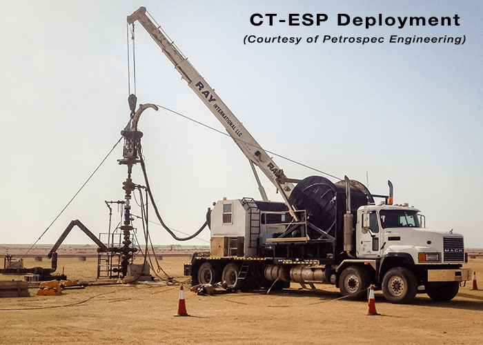
It sounds so tempting. If your oil production depends on electric submersible pumps (ESPs), wouldn’t you like to eliminate the need for workover (WO) rigs? Just imagine it: no rig mobilisation time (or cost!), minimal deferred (lost!) oil. When an ESP fails, simply mobilise a Coiled-Tubing Unit (CTU). Pull and replace your “CT-ESP” under live well conditions… No downtime for well kill operations, no risk of formation damage… Equipment is available “off-the-shelf” from the two largest ESP vendors (well, almost – don’t expect next-day delivery!), not to mention a plethora of bespoke solutions from smaller engineering companies… In short, something for everyone.
Why then, have so few Operators actually embraced CT-ESPs? That’s what I want to explore in this article. But first let’s back up a moment and talk about the technology itself. What exactly is a CT-ESP and how does differ from a conventionally configured ESP deployed on the production tubing?
In this first of a two-part blog, I will summarise the history of their development (did you know they’ve been around for decades?) and describe the current status of this technology. In Part 2 I will discuss application, benefits and of course, the limitations of CT-ESPs before attempting to answer the question posed in the title.
Technology Overview
The first rigless ESP completions were deployed in the 1960’s on cable. However, operational difficulties were frequently encountered. Over time, cable technology gradually improved but even in the 1990’s the general consensus was that further refinement of the cable was still necessary[1]. This led to an interest in other deployment methods including CT-ESP[2], in part because CT servicing techniques were also expanding at this time.
Early CT-ESP completion configurations simply replaced the production tubing with CT: the ESP Power Cable was strapped to the outside of the CT and production flowed up the inside of the CT. The only significant modification to the ESP assembly was the requirement for a connector head between Coil and pump. These “cable-external” systems are still available and are best suited to relatively large CT (typically 2-7/8” or 3-1/2”); in practice, application is usually are limited to low rate, shallow depth wells.
More recently, CT-ESP suppliers have developed “cable-internal” systems: the Power Cable is pre-installed inside the CT and is protected from mechanical damage during deployment and also from reservoir fluids during production. The flow path to surface is via the annular space between CT and either a larger, (pre-deployed) tubing string or the production casing. An inverted (bottom-intake) ESP is required, as are specialised electrical connections at both the downhole and surface end of the Power Cable. This larger annular flow area facilitates higher production and has wider application compared to cable-internal systems.
Figure 1 below compares the two systems:
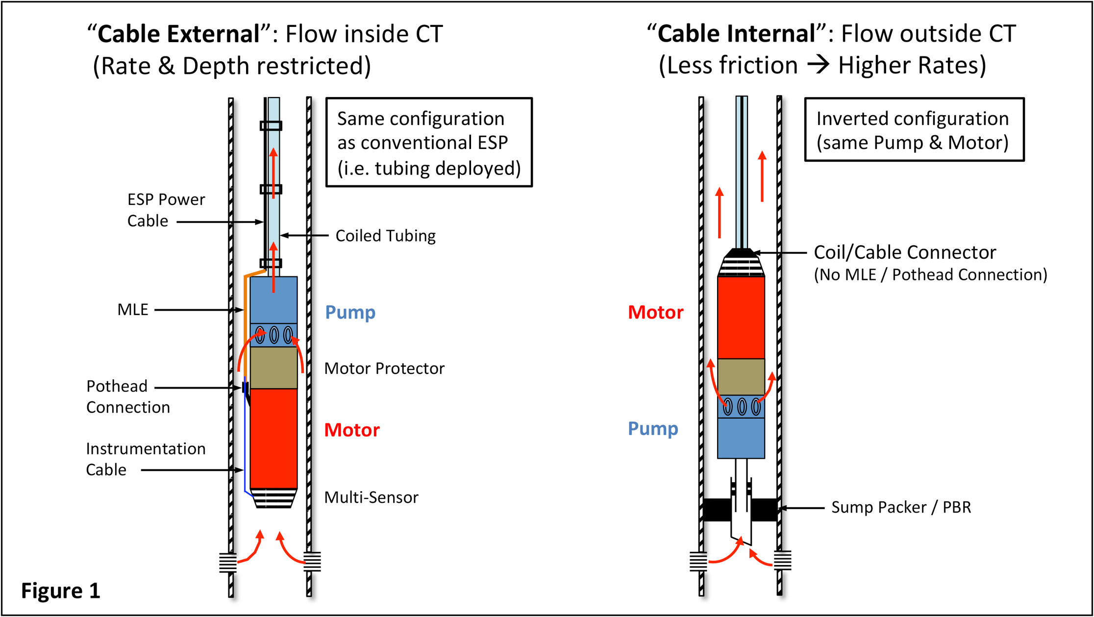
Cable-internal systems require some kind of flow isolation device below the ESP such as a sump packer. This is to ensure all fluids pass through the pump, which in this case discharges into the annulus. (Both systems require adequate flow – a high enough velocity of reservoir fluids – past the motor to ensure it is kept sufficiently cooled.) For gassy wells a gas-handling device is required because it is not possible to include a gas separator.
The inverted ESP configuration does not require a motor lead extension (MLE) or conventional pothead connection; this is a major benefit because the OD of the made-up ESP assembly is reduced and a potential (electrical) failure location is eliminated.
Placing the Power Cable inside the CT simplifies the deployment process; the need to secure the Power Cable to the CT and to have Power Cable Spooling equipment on-site is eliminated, i.e. smaller footprint compared to cable-external systems.
Live-well deployment: installation through a lubricator or snubbing unit is possible because the OD of the CT is smooth and concentric. (Use of an annular preventer for well control is also feasible.) No rig is required, only a CT Spooler and Injector Head need be deployed. Run-in speeds of 30 m/min are possible, significantly reducing deployment time.
Two key challenges facing the developers of this technology are 1) how the Cable is supported inside the Coil and 2) how to hang-off the Coil at the surface in a manner that allows an electrical connection to the Power Cable while guaranteeing an effective pressure seal in the Wellhead.
ESP Power Cable is unable to support itself vertically (hence the limitation of external systems); its own weight will cause it to buckle. Manufacturers have tried various ways to address this issue, including placement of a buoyancy fluid inside the Coil to support the Power Cable. Others have relied on mechanical support such as anchors, or even adapted the relative sizing of the Power Cable and Coil to allow some natural, helical buckling to occur. At least one manufacturer offers a custom-built, composite Power Cable umbilical that is packaged inside the CT.
As for the Wellhead, the easiest way to deploy and land the CT is again to use a horizontal tree*. In many cases conventional trees can be modified – provided the bore is large enough to accommodate the largest OD of the ESP assembly – by inclusion of an additional spool to facilitate landing the CT between the Wellhead and tree.
[*Horizontal tree design allows the Power Cable to exit the top of the tree through modified crown plugs and a housing adaptor sitting on top of the tree. During ESP change-outs a CT BOP with a lubricator section to accommodate the length of the ESP is positioned above the tree.]
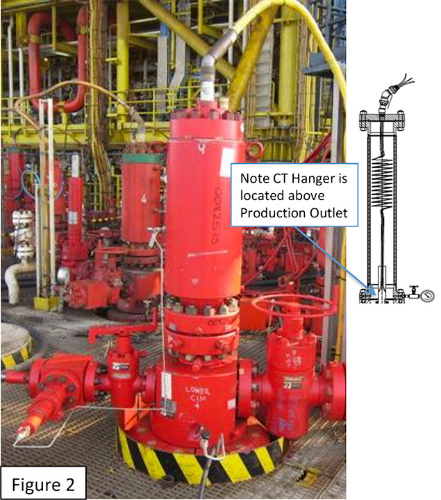
Figure 2 shows a typical configuration of a custom-built spool (often called a Bonnet Extension), flange mounted to a horizontal tree. The Power Cable exits the CT and connects to the tree cap penetrator inside the Bonnet Extension. Note how the CT hanger lands in a profile above the production outlet. During WO operations, after the Bonnet Extension is removed and the BOP fitted, the Coil (hanger, Coil and ESP) can then be retrieved through the tree bore.
So that’s the technology overview. In Part 2 I will discuss application, benefits and of course, the limitations of CT-ESPs to help you decide whether CT-ESPs are worth considering for your field.
[1] SPE-14187, SPE-25571
[2] OTC-7035, OTC-7322